A STEP-BY-STEP MANUAL FOR BUILDING BIO-STRIPS OF YOUR CHEMICAL REACTION
Note that for building bio-Strips that would allow a reliable estimation of possible harmful impact of your reaction on living organisms, the cytotoxicity of all the compounds participating in this reaction should be measured in the same cell line at the same exposure time by using the same experimental assay. Only in this case, the comparison will be informative.
The source file is a file in a .txt format that contains the data required for building bio-Strips for a given chemical reaction. In particular, these data include: 1) the cell line, in which the cytotoxicity (half-maximal cytotoxicity concentration, CC50) was assayed; 2) the reagents being varied in the reaction; 3) the variable reagents, upon which the resulting (by)products depend; and 4) a list of all the substances entering or leaving the reaction, including their role, molecular weight, mass used in the reaction, and CC50 in the corresponding cell line.
There are two ways to create a source file: by using a dedicated form in the “Build Charts” tab (click "create file" for opening the corresponding form) and by completing the .xlsx template (provided in the “Manual” tab) and subsequently saving it in a .txt (tabulation-separated, UTF-8) format. The detailed instructions are provided below.
You can download the .xlsx template for filling in the data here.
General information
Whether you are using the form or creating the source file manually, the most important step of the process is to designate the substances correctly. The correct designation of the substances allows calculating all the possible combinations of the reaction correctly. Usually, numerous ways of synthesizing a particular target product upon varying particular reaction compounds are considered.
Each substance plays its own role in the reaction, and this role is encoded by its abbreviated title:
SM (starting material), CT (catalyst), R (reagent), S (solvent), P (product), and BP (byproduct)
For constant substances (those that are not varied in the ways of synthesis of a particular product), the following notation is used:
Ni (e.g. SM1, SM2, R, S etc.)
where i is the order number.
If the substance is being varied, the following notation should be employed:
Ni-k or N-i (e.g. SM1-1, SM1-2, SM2-1, SM2-2, R-1, R-2, S-1, S-2, etc.)
If there is only one substance with a particular role in the reaction (for example, one catalyst or one solvent), it is designated as N (for constant substances; e.g. R, S) or N-i (for variable substance; e.g. R-1, R-2, S-1, S-2).
Usually, there is one target product in the reaction, and it does not depend on the variable substances. Therefore, the product is designated as P. However, the variable substances decide the byproducts being formed:
BPi-k-l-m-…
where i is the order number of the byproduct, and k, l, m, etc. are the order numbers of the substances upon which the byproduct depends (e.g. SM1-k, SM2-l, SM3-m, etc.).
If a particular byproduct does not depend on a particular variable, 0 is used instead of the corresponding order number:
BPi-k-0-m-… (the byproduct does not depend on variable SM2)
In a more complex case, when one byproduct can be formed upon using various combinations of reagents, the following notation should be used:
BPi-k-l/n-m-… (the same byproduct is formed upon using SM2-l or SM2-n)
Dependent variables: general case
Here, starting materials (SM) are used as an example but the scheme is valid for reaction substances with other roles (CT, R, S, etc.). In a general form, the notation of a starting material looks as follows:
SMi-j-k,l,m,…
where i is the order number of the type of a given reagent, j is the order number of the reagent of this type, and k, l, m, etc. are the order numbers of substances SMi-1, with which this substance reacts (Figure 1).
In this case, the data should form a head-to-tail structure: if you have several reagents of type 1 (SM1-1, SM1-2, etc.), then reagents of type 2 should be designated as follows:
SM2-i-1 (if this reagent reacts only with SM1-1), SM2-i-2 (if this reagent reacts only with SM1-2), or SM2-i-1,2 (if this reagent reacts with both SM1-1 and SM1-2)
Accordingly, reagents of the next type should have the following notation:
SM3-i-1 (if this reagent reacts with SM1-1 and SM2-1-1), SM3-i-2,3 (if this reagent reacts with the pairs SM1-1/SM2-2-1 and SM1-2/SM2-3-2), or SM3-i-1,2,3,4 = SM3-4 (if the reagent reacts in all possible combinations).
Thus, each combination represents the sequence of graph nodes from the parent element to the terminal daughter element, whereas the notation of a particular substance is the summation of all the combinations available for this substance.
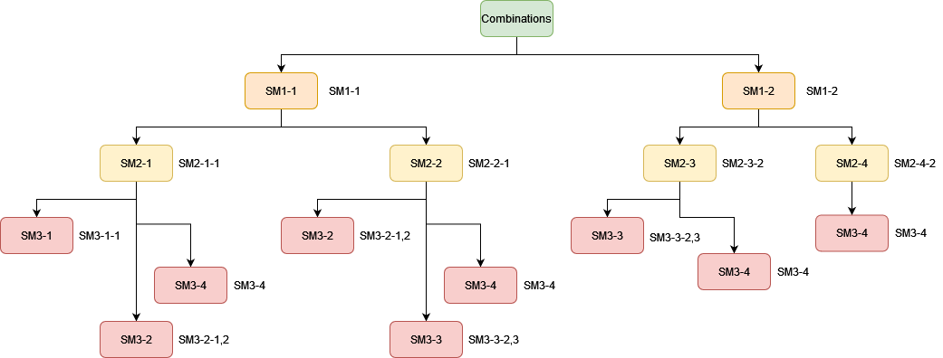
Figure 1. A tree of combinations of substances in a three-component reaction. The substances of the same type are shown by the same color; their notations are given on the right.
Here, we will explain the creation of a source file by example of synthesis of 4-nitro-1,1’-biphenyl (Figure 2). In this example: the following substances are being varied: starting material 2 (SM2: 1-iodo-4-nitrobenzene (A), 1-bromo-4-nitrobenzene (B), or 1-chloro-4-nitrobenzene (C)), catalyst (CT: Pd(OAc)2 (A), PdCl2 (B), or Pd(acac)2 (C)), reagent (R: Na2CO3 (A), K2CO3 (B), or Cs2CO3 (C)), and solvent (S: ethanol (A) or NMP (B)). Accordingly, the first, second, third, and fourth letters in the reaction name correspond to the type of starting material 2 (SM2), catalyst (CT), reagent (R), and solvent (S) being used: SM2-CT-R-S.
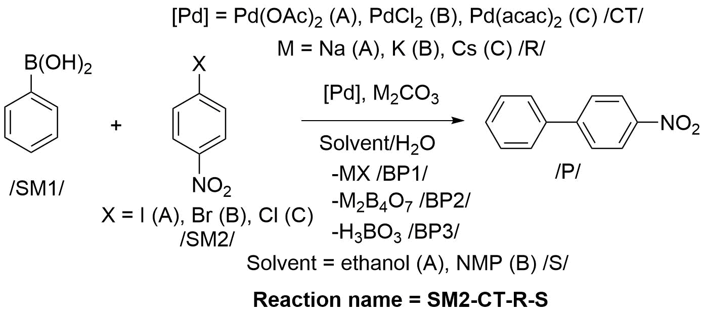
Figure 2. Scheme of synthesis of 4-nitro-1,1’-biphenyl. The first, second, third, and fourth letters in the reaction name correspond to the following variable substances: starting material 2 (SM2: 1-iodo-4-nitrobenzene (A), 1-bromo-4-nitrobenzene (B), or 1-chloro-4-nitrobenzene (C)), catalyst (CT: Pd(OAc)2 (A), PdCl2 (B), or Pd(acac)2 (C)), reagent (R: Na2CO3 (A), K2CO3 (B), or Cs2CO3 (C)), and solvent (S: ethanol (A) or NMP (B)).
We find it convenient to create an .xlsx template first and then convert it to the .txt format. Figure 3 shows the corresponding template for the reaction provided in Figure 2. Here, the first line (field “Cell”) contains the name of the cell line, in which CC50 of the substances was determined; the second line (field “Variables”) contains the reagents being varied in the reaction (in this case – SM2, CT, R, and S); and the third line (field “Product variables”) contains the variable reagents (SM2, R), upon which the resulting byproducts depend. Below is the table containing the information about all the substances participating in the reaction, distributed into groups in accordance with their role. This information includes their name (field “Samples”), role in the reaction (field “Abbreviation”: starting material (SM), catalyst (CT), reagent (R), solvent (S), product (P), or byproduct (BP)), molecular weight (Mr, g/mol), mass (g) used in the reaction, and CC50 (mM) in the corresponding cell line.
The substances participating in the reaction or forming upon its course are designated in accordance with the above-mentioned rules (see column “Abbreviation” in Figure 3)
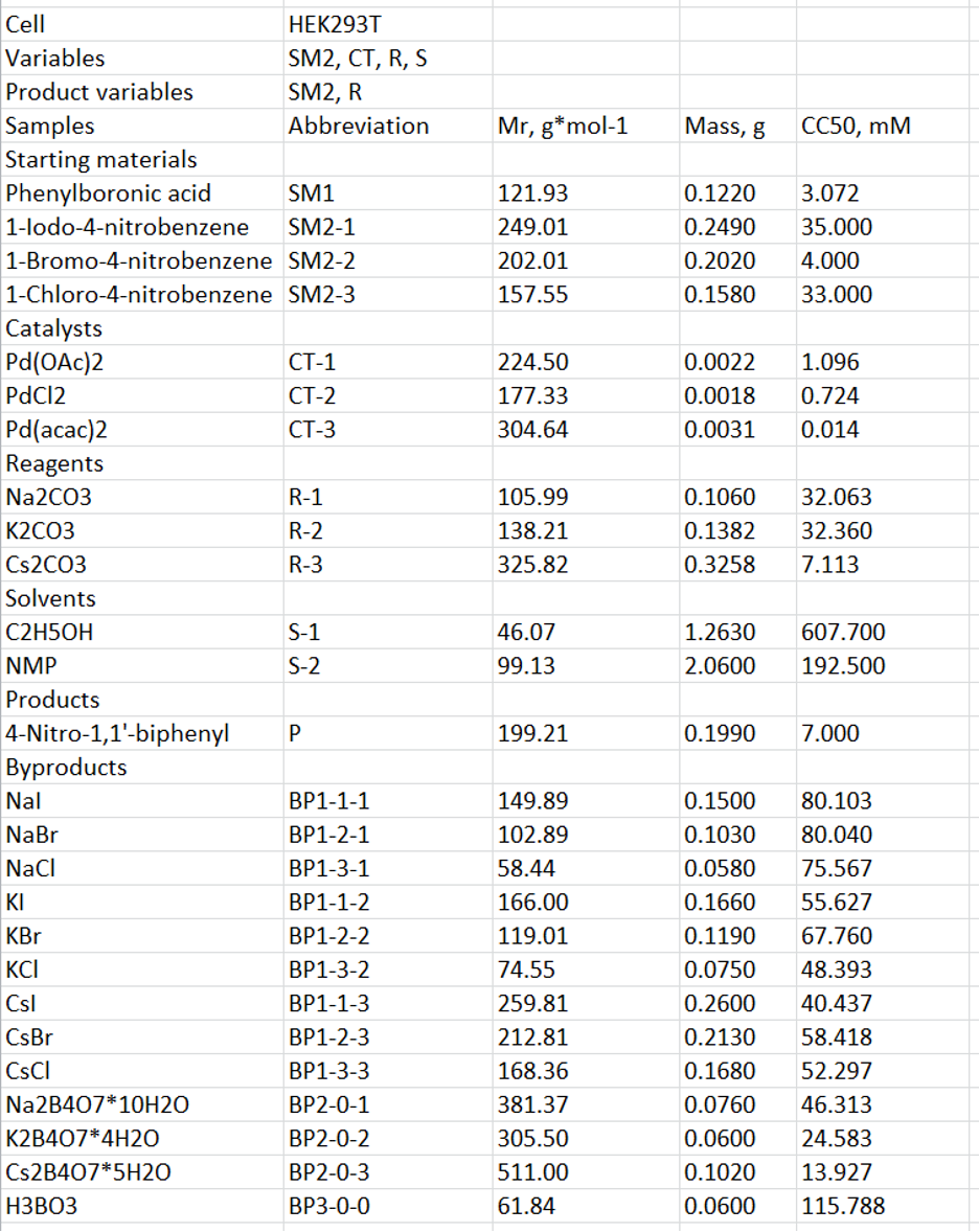
Figure 3. An .xlsx template used for creating a .txt source file for synthesis of 4-nitro-1,1’-biphenyl. The first line contains the name of the cell line, in which CC50 was determined; the second line contains the reagents being varied in the reaction (in this case – SM2, CT, R, and S); and the third line contains the variable reagents (SM2, R), upon which the resulting byproducts depend. Below is the table containing the information about all the substances participating in the reaction. This information includes their role in the reaction (starting material (SM), catalyst (CT), reagent (R), solvent (S), product (P), or byproduct (BP), molecular weight (g/mol), mass (g) used in the reaction, and CC50 (mM) in the corresponding cell line.
Starting materials
There are two types of starting materials in this reaction: the constant substance SM1 (phenylboronic acid) and the variable substance SM2. The latter implies 1-iodo-4-nitrobenzene, 1-bromo-4-nitrobenzene, and 1-chloro-4-nitrobenzene, which are designated, correspondingly, SM2-1, SM2-2, and SM2-3.
Catalysts, reagents, and solvents
There is one type of catalyst in the reaction, and this substance is variable; therefore, it is designated as CT-1 (Pd(OAc)2), CT-2 (PdCl2), or CT-3 (Pd(acac)2), respectively. The same is true for the reagents (R-1, Na2CO3; R-2, K2CO3; and R-3, Cs2CO3) and solvents (S-1, C2H5OH; and S-2, NMP).
Products
The target product 4-nitro-1,1’-biphenyl is designated P.
Byproducts
In this reaction, three types of byproducts are produced: (1) halides of sodium, potassium or cesium, (2) tetraborates of sodium, potassium or cesium, and (3) boric acid. The first type of byproducts depends on both the type of starting material 2 (SM2) and the reagent (R) being used and thus is designated as follows: BP1-k-l, where k corresponds to the order number of SM2 (1 = SM2-1 = 1-iodo-4-nitrobenzene; 2 = SM2-2 = 1-bromo-4-nitrobenzene; and 3 = SM2-3 = 1-chloro-4-nitrobenzene) and l corresponds to the order number of R (1 = R-1 = Na2CO3; 2 = R-2 = K2CO3; and 3 = R-3 = Cs2CO3). In whole, there are nine BP1 possible in this reaction: NaI (BP1-1-1), NaBr (BP1-2-1), NaCl (BP1-3-1), KI (BP1-1-2), KBr (BP1-2-2), NaCl (BP1-3-2), CsI (BP1-1-3), CsBr (BP1-2-3), and CsCl (BP1-3-3).
The second type of byproducts depends only on the type of the reagent being used and thus is designated as follows: BP2-0-l, where l corresponds to the order number of R (1 = R-1 = Na2CO3; 2 = R-2 = K2CO3; and 3 = R-3 = Cs2CO3). There are three BP2 possible: Na2B4O7*10H2O (BP2-0-1), K2B4O7*4H2O (BP2-0-2), and Cs2B4O7*5H2O (BP2-0-3).
Finally, the third byproduct (BP3) is produced independently of the reagents used in the current example and thus is designated BP3-0-0.
The columns “Mr, g/mol”, “Mass, g”, and “CC50, mM” contain the molecular weight (g/mol), mass (g) used in the reaction, and CC50 (mM) for each substance.
The completed template can be subsequently saved in a .txt (tabulation-separated, UTF-8) format, which can be directly uploaded to the server for building bio-Strips by following the instructions in the “Build Charts” tab. The detailed explanation of the procedure is given below in the “How to build bio-Strips for your reaction” section. Figure 4 shows an overview of a .txt source file created from the template provided in Figure 3.
Figure 4. An exemplary .txt source file for bio-Strips for synthesis of 4-nitro-1,1’-biphenyl. The first line contains the name of the cell line, in which CC50 was determined; the second line contains the reagents being varied in the reaction; and the third line contains the variable reagents, upon which the resulting byproducts depend. Below is the table containing the information about all the substances participating in the reaction.
You can also create a source file by using a dedicated form provided in the “Build Charts” tab (click "create file" for opening the corresponding form). An overview of this form is shown in Figure 5. The top part of the form is common for all the reactions being considered. It contains the following fields:
“Cell name” – the name of the cell culture, in which CC50 values were measured.
“Colormap” – the type of coloration used in the resulting bio-Strips; currently, two colormaps are available: percentile (the cytotoxicity scale is colored in accordance with the percentile distribution of the CC50 values, where the midpoint corresponds to the 50th percentile) and linear (the cytotoxicity scale is colored in accordance with the distribution of the CC50 values, where the midpoint corresponds to the mean value).
“Cytotoxic potential” – the type of the cytotoxicity metrics by which the obtained bio-Strips are evaluated and the five top variants are selected. The following metrics are available: BF (bio-Factor, shows the change of the “overall cytotoxicity” of a given reaction during its course; it is considered increased if BF > 1 or decreased if BF < 1); CPi (initial cytotoxicity potential, or CP of the substances entering the reaction); CPf (final cytotoxicity potential, or CP of the substances leaving the reaction), and CPf_rel (relative final cytotoxicity potential, or CP of the substances leaving the reaction except for the target product). In essence, CPs show the quantity of the liters of the cell media that can be “poisoned” by the corresponding substances. The formulas for calculating the metrics are provided below. NC is a “normalized cytotoxicity” of a particular substance, n is the amount (mmol) of a particular substance in a given reaction, and CC50 is a half-maximal cytotoxicity concentration of a given substance measured in a particular cell line; in and out designate the substances entering (starting materials, catalysts, solvents and other reagents) or leaving (products, byproducts and chemicals that can be recycled, such as catalysts and solvents) the reaction, accordingly.
$$NC = {n \over CC_{50}}\ (1)$$ $$BF = {\sum NC_{out} \over \sum NC_{in}} = {\sum {n \over CC_{50}(out)} \over \sum {n \over CC_{50}(in)}}\ (2)$$ $$CP_i = {\sum NC_{in}}\ (3)$$ $$CP_f = {\sum NC_{out}}\ (4)$$ $$CP_{f\_rel} = {\sum NC_{out} - NC_{product}}\ (5)$$“Variables” – the variable substances in the reaction under consideration.
“Product variables” – the variable substances deciding the byproducts being formed in the reaction.
“Variable dimension” – units of measure of toxicity values being used (mol·kg-1 or mol·L-1, g·kg-1 or g·L-1).
The bottom part of the form shown in Figure 5 includes the information on the particular substances participating in the reaction under consideration. For each of the compounds entering or leaving the reaction, the following fields should be completed: “Reagent name”, “Role”, “Molar mass”, “Mass”, and “CC50”. These fields correspond to the fields in the table shown in Figure 3 and include the name of the substances, their role in the reaction (starting material (SM), catalyst (CT), reagent (R), solvent (S), product (P), or byproduct (BP), molecular weight (g/mol), mass (g) used in the reaction, and CC50 (mM) in the corresponding cell line. Instead of CC50, experimental or predicted LD50 values can be used. In the latter case, SMILES should be provided for all the substances in the reaction and the corresponding LD50 are calculated by using a baseline prediction model. To achieve better performance, users can provide their custom models. There are two separate forms, first of which is completed for starting materials, catalysts, reagents, and solvents, and the second is for products and byproducts. Additional substances can be added by pressing the “Add new reagent” or “Add new product” button.
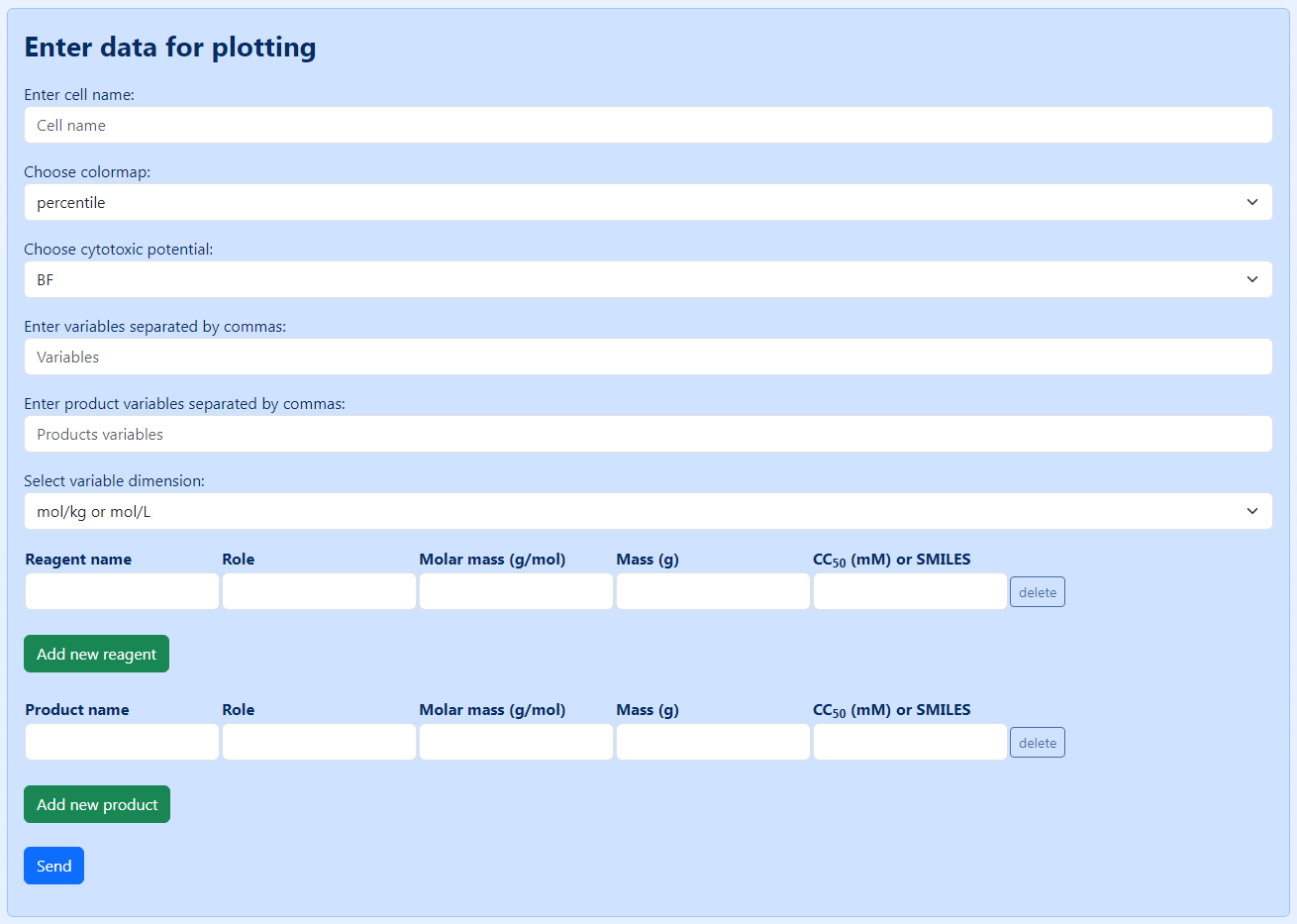
Figure 5. An overview of the form for creating a source file.
Figure 6 shows the completed form for synthesis of 4-nitro-1,1’-biphenyl provided in Figure 2. For considerations used for the designation of substances, see the section “How to create a source file manually”. Pressing the “Send” button starts the process of calculating all possible reaction combinations and building the corresponding bio-Strips.
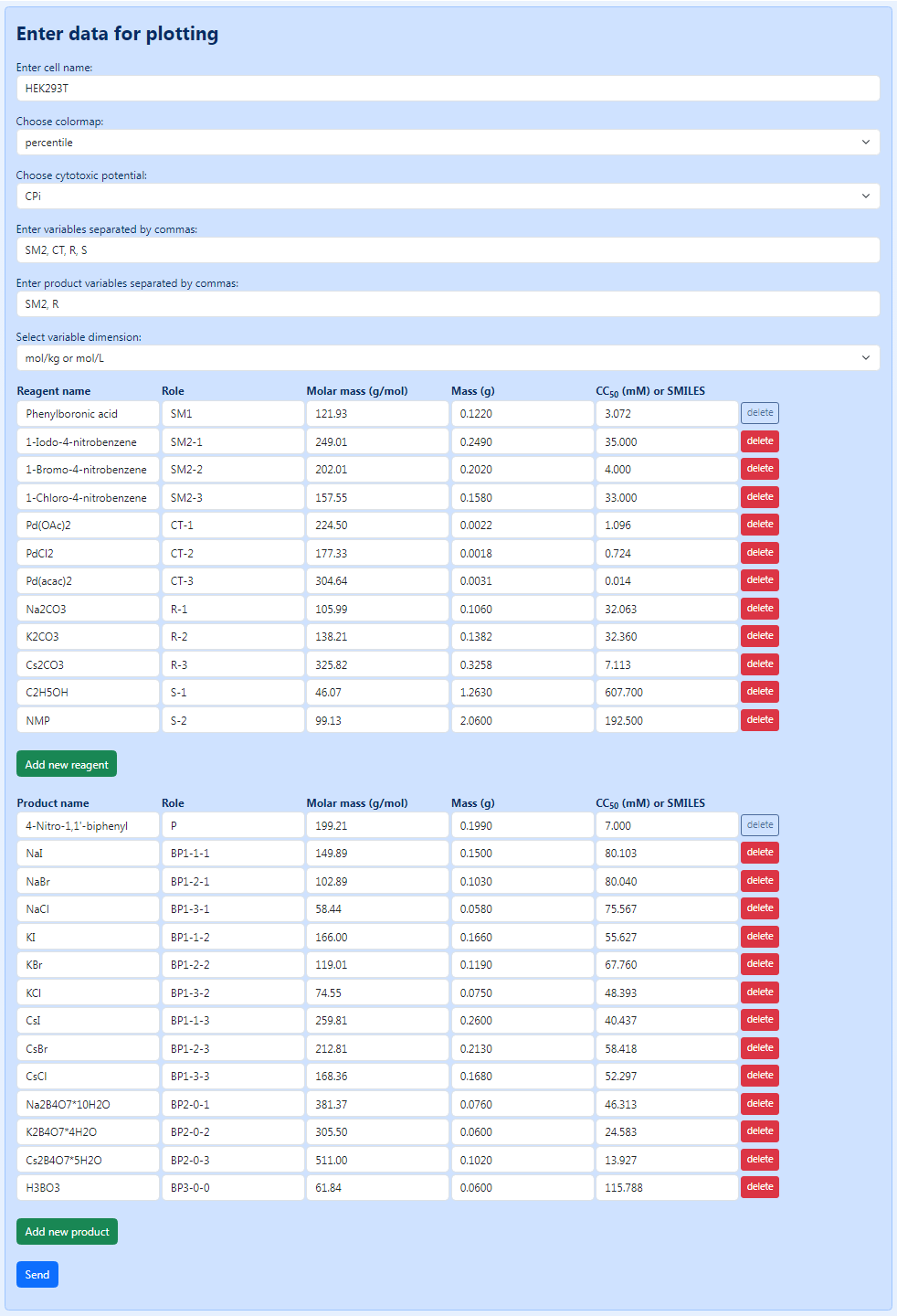
Figure 6. An overview of the form completed for synthesis of 4-nitro-1,1’-biphenyl (see Figure 2).
Here, we will describe the process when using a manually created .txt source file. When using the dedicated form, it is essentially the same but the source file is generated and uploaded to the server automatically.
To upload the source file to the server, go to the “Upload file and select options” form in the “Build Charts” tab and provide the information required: choose the source file and select the colormap, cytotoxic potential, and variable dimension (the detailed description of the last three parameters is provided in the section “How to create a source file by using a dedicated form”) (Figure 7, top form). Then press the “Send” button. After this, if the source file does not contain any errors, the “Build Charts” will show the “Filename” (Figure 7, bottom form) - a unique id, which can be subsequently used for retrieving this run quickly (see the “Previous runs” tab in the menu).
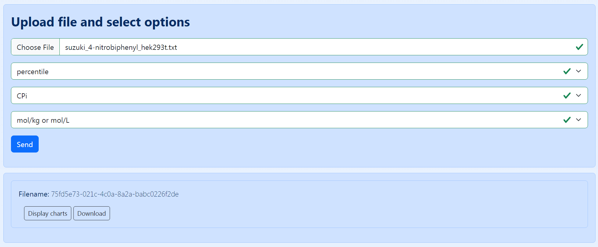
Figure 7. An overview of the form for uploading a manually created source file. In this case, “percentile” and “CPi” are selected as the colormap and cytotoxic potential, respectively.
Pressing the “Display charts” button will show the resulting bio-Strips. Figure 8 shows a part of the resulting page with bio-Strips for 54 ways of synthesis of 4-nitro-1,1’-biphenyl, in accordance with the source file provided in Figure 4. The five top combinations with the lowest CPi are shown above (in this case, all these CPi equal 0.44). The cytotoxicity scale colored in accordance with the percentile distribution of the CC50 values is also provided. The bio-Strips are supplied with the reaction title and BF.
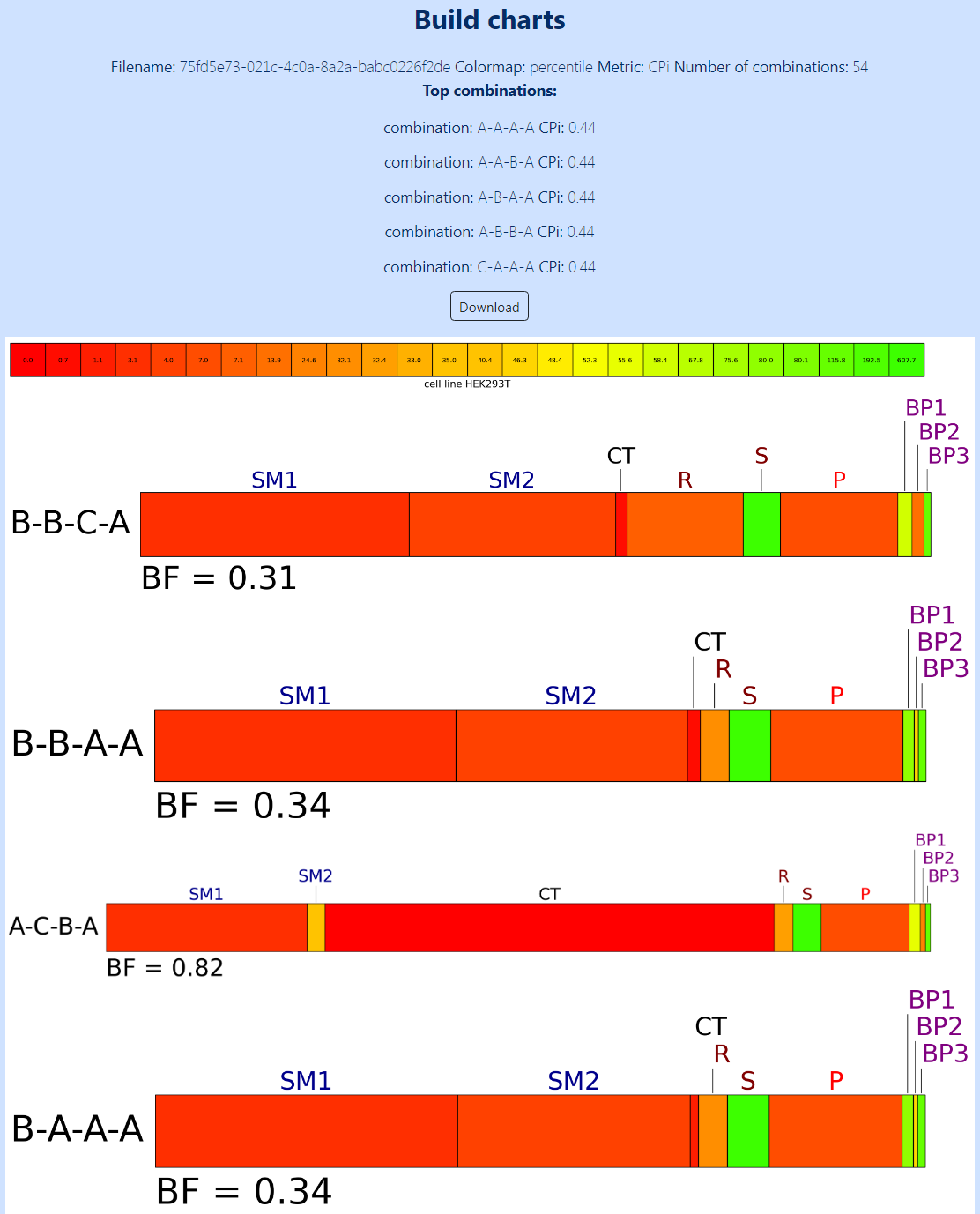
Figure 8. A part of the resulting page with bio-Strips for 54 ways of synthesis of 4-nitro-1,1’-biphenyl, in accordance with the source file provided in Figure 4. The five top combinations with the lowest CPi and the cytotoxicity scale colored in accordance with the percentile distribution of the CC50 values are shown above. The length of the sections in the bars corresponds to the “normalized cytotoxicity” (NC) of the substances, whereas their color corresponds to CC50 measured in the HEK293T cell line. The bio-Strips are supplied with the reaction title and BF. Only four of 54 bio-Strips are shown for clarity.
Pressing the “Download” button downloads a .zip archive of the results which contains two folders: “data” and “results”. The “data” folder contains the .txt source file used for building the bio-Strips and a .csv file with the legend for the reaction names and toxicity values used (Figure 9).
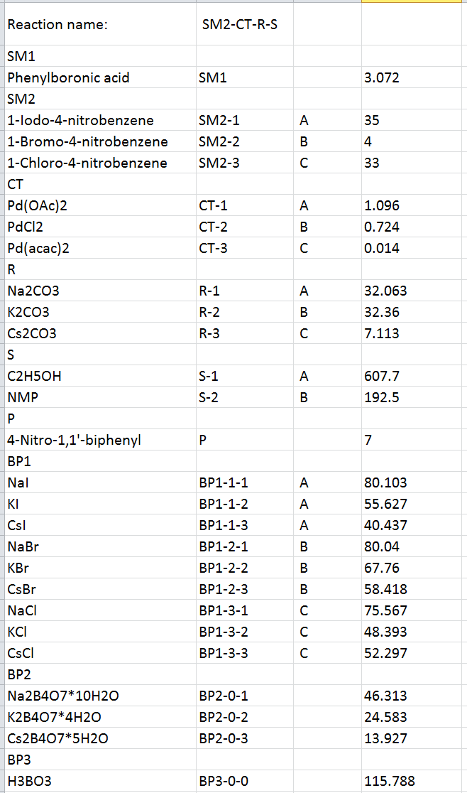
Figure 9. The resulting .csv file with the legend for the reaction names.
The “results” folder contains separate bio-Strips in .pdf, .png, and .svg formats, and a .csv file with the calculated cytotoxicity metrics (BF, CPi, CPf, and CPf_rel) (Figure 10).
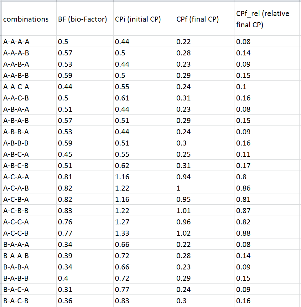
Figure 10. A part of the resulting .xlsx file with the calculated metrics for the above-considered reactions.
The separate bio-Strips can be subsequently combined for illustration purposes (see an example provided in Figure 11).
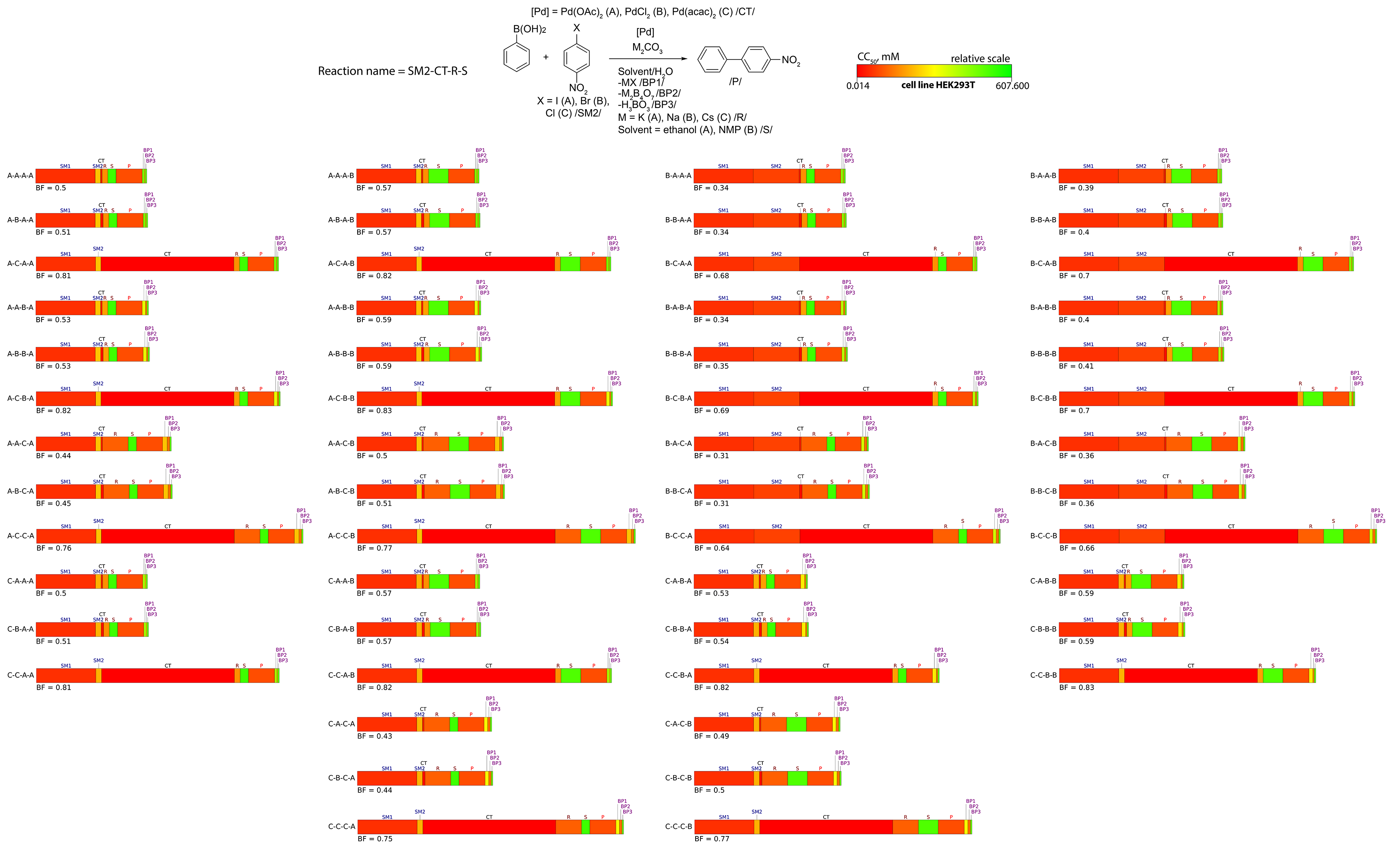
Figure 11. bio-Strips of 54 ways of synthesis of 4-nitro-1,1’-biphenyl upon varying starting material 2 (SM2: 1-iodo-4-nitrobenzene (A), 1-bromo-4-nitrobenzene (B), or 1-chloro-4-nitrobenzene (C)), catalyst (CT: Pd(OAc)2 (A), PdCl2 (B), or Pd(acac)2 (C)), reagent (R: Na2CO3 (A), K2CO3 (B), or Cs2CO3 (C)), and solvent (S: ethanol (A) or NMP (B)). CC50 values are measured in the HEK293T cell line.
When experimental values are unavailable, users may resort to using predictive models. On our platform, we provide a baseline model trained on a large dataset of small organic molecules from LDToxDB (Feinstein et al., 2021, J. Chem. Inf. Model, 61, 5793). The model achieves a decent R2 value of 0.54 for this task (Figure 12). To use the model, simply provide SMILES instead of CC50.
For cases where the accuracy of predictions is critical, we suggest that users supply their own custom model, trained on custom data collected under controlled, fixed conditions. Still, given current state of the field, experimental data remains the best option.

Figure 12. Performance of the model: comparison of predicted and ground truth values on a test set (left) and examples of predictions (right).